Differential probes

Home > Products > Measuring Instrument > Differential probes > Details
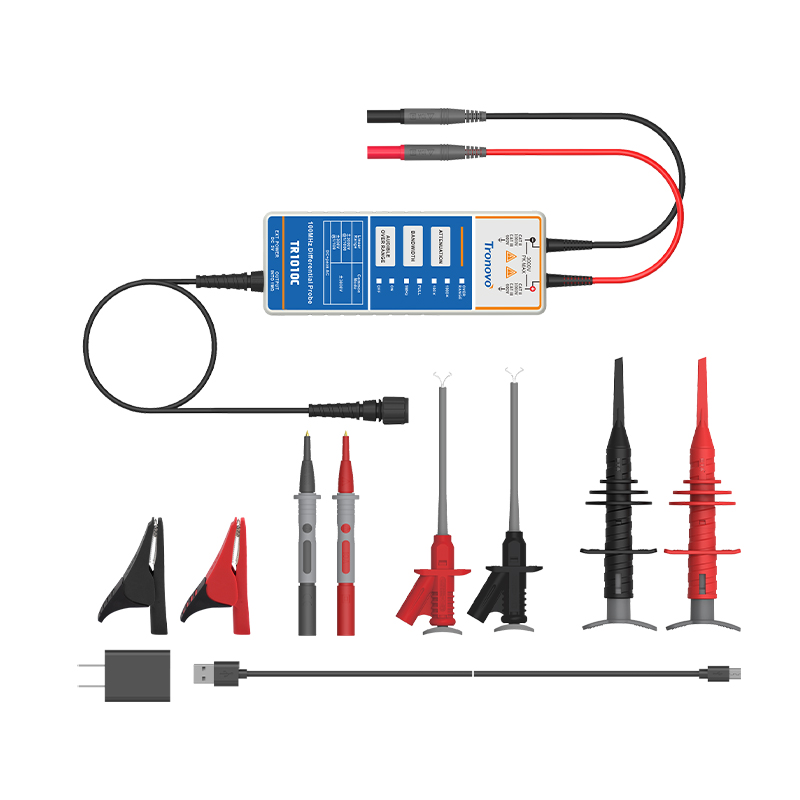
100MHz/1300V High Voltage Differential Probe

100MHz/1300V High Voltage Differential Probe

0
This economical high-voltage differential probe features ±1300 V differential range, 100 MHz bandwidth and switchable 50×/500× attenuation for mainstream high-voltage floating tests. High input impedance reduces circuit loading, and the built-in overvoltage indicator ensures safe operation. With core measurement functions preserved and auxiliary circuits simplified for better cost efficiency, it is ideal for routine high-voltage measurements.
Performance
❯ Motor drive and VFD testing
❯ Power converter & inverter analysis
❯ Switching power supply design & debugging
❯ High-voltage floating signal measurement & troubleshooting
Key Features
❯ Standard BNC output connector
❯ Covers most high-voltage test scenarios
❯ High input impedance to minimize impact on the circuit under test
❯ Meets basic high-voltage test requirements at an economical price
Downloads

You may also be interested in these products

Product Parameter

  • Model
  • TR1010
  • Bandwidth (-3dB)
  • 100 MHz
  • Rise Time
  • ≤3.5 ns
  • Accuracy
  • ±2%
  • Range (Attenuation)
  • 50×/ 500×
  • Max. Differential Voltage (DC+Peak AC)
  • 50× ±130V / 500× ±1300V
  • CMV, DC + Peak AC
  • ±1300V
  • ax. Input to Ground (Vrms)
  • 600 V CAT III 1000 V CAT II
  • Input Impedance
  • Single-Ended (to GND): 4 MΩ ±1% / Two Inputs: 8 MΩ ±1%
  • Input Cap
  • Single-Ended (to GND): <7 pF / Two Inputs: <3.5 pF
  • CMRR
  • DC:>80 dB / 100 kHz: >60 dB / 1 MHz: >50 dB

Product Details

1689235810411851.png

Upgraded Differential Probe

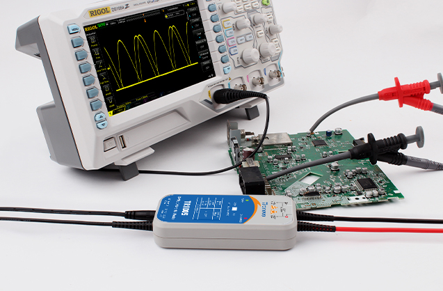
BNC interface differential probe supports CAT II 1000V safety specification and can withstand 1300V high voltage at most, providing safe floating ground measurement for new energy vehicle electronic control system and photovoltaic inverter. The probe has a built-in overload alarm function, and abnormal voltage triggers sound and light prompts to ensure the safety of high-power testing. Compatible with oscilloscope 1MΩ input impedance settings, suitable for inverter and UPS power supply fault diagnosis.

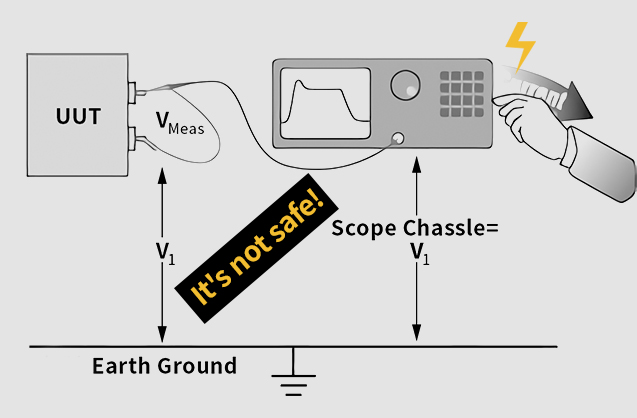
Advantages of differential measurement

The differential probe supports 4-channel synchronous measurement of LLC resonant power supply. The primary MOSFET and the secondary rectifier tube belong to different ground potentials, and the isolation withstand voltage between the probes is> 2500 V/mm, thus completely solving the risk of "explosion" caused by the common ground of multiple probes. The two-gear attenuation ratio switching function (50:1/500:1) is suitable for cross-level safety diagnosis of 20V drive to 1000V main circuit.

1682751213592601.jpg
1682751239835596.jpg

CMRR Common Mode Rejection Capability

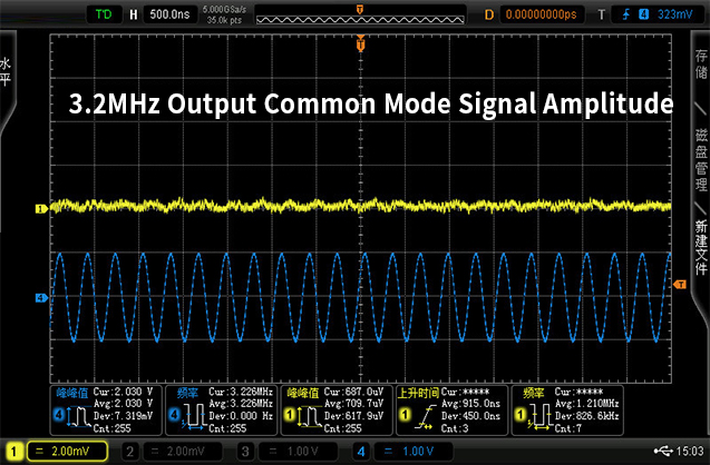
For the three-phase non-common ground signal U-V-W by 380V inverter, the input impedance balance error of differential probe is less than 0.5dB, and TVS overvoltage protection combined with acousto-optic alarm mechanism can prevent short circuit accidents caused by grounding clamp touching high-voltage bus by mistake. The power frequency suppression capability of 80dB @ 50Hz strips off the high frequency harmonic interference of the induction cooker and truly restores the IGBT gate drive waveform.

Rich accessories

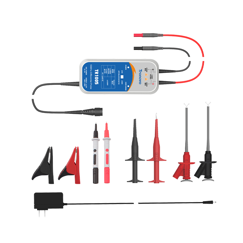
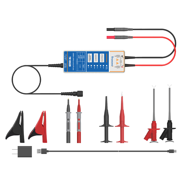
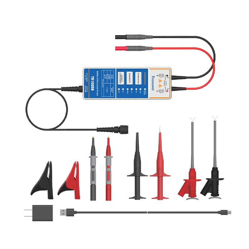
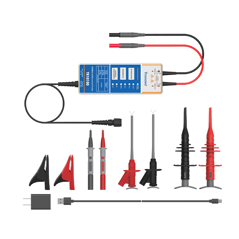
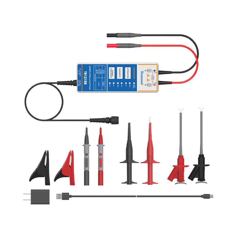
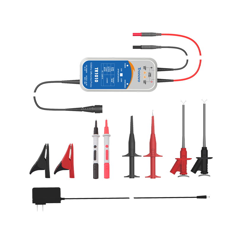
The differential probe is equipped with four professional accessories: alligator clip, telescopic clip, precision probe and aircraft hook to create a full-scene signal access scheme. The gold-plated contact of the crocodile clip realizes low-noise grounding and high-voltage test reliability. The telescopic clip is adapted to dense wiring; The submicron needle tip of the precision probe accurately captures the chip signal. The spring-loaded structure of the aircraft hook quickly hooks and efficiently captures the dynamic waveform of high-frequency power supply.

1682751269879445.jpg
1682751335156602.jpg

Noise test

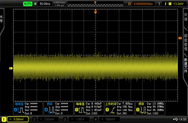
Short-circuit the input of the probe to form a zero potential reference point, and start the bottom noise measurement mode after the output is connected to the oscilloscope channel. The test scheme uses a differential architecture to suppress common-mode interference, combined with an ultra-low noise preamplifier and a metal-shielded housing, to accurately quantify the inherent noise floor of the probe. Typical noise floor ≤ 30mVrms (within 20MHz bandwidth), ensuring that nanosecond signal details can still be clearly resolved in high-noise environments such as switching power supplies and motor control.

.

Product Video

TAG:

Related Articles